Free-Flex® Flexural Pivot Engineering Data
Comprehensive engineering reference: load ratings (Vc/Vt), torsional spring rates, dimensional data, materials, and terminology for all 30 standard pivot configurations across 10 diameters.
Patented Flexural Pivot
RIVERHAWK produces the patented FREE-FLEX® flexural pivot for aerospace, commercial and industrial bearing applications involving limited angular travel. As an alternative to rolling element bearings, the FREE-FLEX® pivot offers superior operating characteristics with demonstrated performance and installed cost advantages.
It is a frictionless, stiction-free bearing ideally suited for angular deflection (rotation) of up to 60°. Compact and easily installed, it provides high radial stiffness (up to 100,000 lb/in), no backlash, no metal-to-metal contact, and predictable, repeatable performance. Adjustments in 0.00005-inch increments can be made with no lost motion.
The pivot consists of flat springs crossed at 90° supporting cylindrical counter-rotating sleeves. Because there is no metal-to-metal contact, friction, stiction, fretting corrosion, lubrication, "space welding", and lubricant out-gassing in vacuum are all avoided. A FREE-FLEX® pivot was cycled for over 12 billion cycles over twenty years, outliving several test machines.
Configurations & Materials
- • Two mounting configs: cantilevered (overhung load) and double-ended (bridge-supported central load).
- • Stock OD from 0.125" to 1.0", radial loads to 1600 lb.
- • Series 5000 (cantilevered) & Series 6000 (double-ended), each in several torsional spring rates.
- • Bodies: AISI 410 or 420 corrosion-resistant steel. Flexures: AISI 420 SS.
- • Standard assembly by brazing; electron beam welding for elevated temperature.
- • Special materials: Inconel, beryllium copper, titanium.
Covered by U.S. Patents: 3,807,029; 3,811,665; 3,813,089; 3,825,992; 4,327,527, and foreign patents.
Major Performance Characteristics
Major Characteristics
Additional Characteristics
"The Free-Flex® flexural pivot is an elegantly simple bearing which provides precise single-plane positioning and frictionless motion of limited angular rotation devices."
Dimensional Reference
Single-Ended (Series 5000): L = overall length, A = spring section length, D = diameter. Double-Ended (Series 6000): L = overall length, B = end section, C = center section, D = diameter.
Complete Data Tables
All 30 standard configurations · 10 diameters × 3 spring series
L ±0.003", A/B ±0.005" · Spring rate ±10% tolerance · Vc = compression load, Vt = tension load
Centershift vs. Angular Deflection
Centershift is the radial displacement of the moved portion relative to the fixed portion as a function of deflection angle, at no-load conditions.
To determine centershift at any particular angle, multiply the pivot diameter by the respective factor for that angle. The factor increases with deflection angle.
Hysteresis
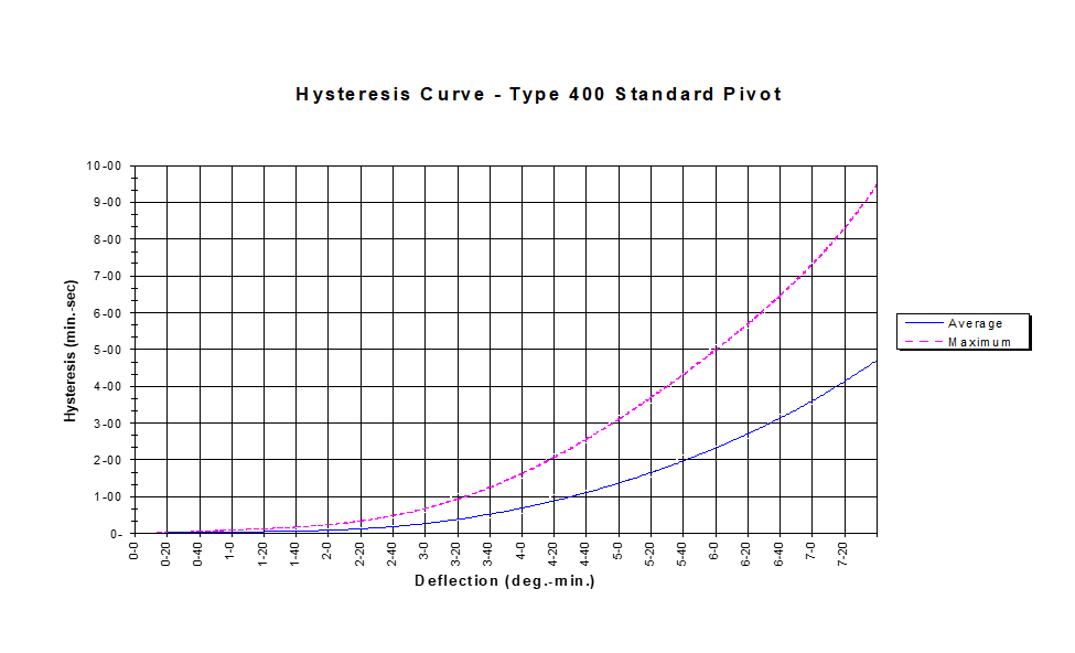
Hysteresis Curve — Type 400 Standard Pivot
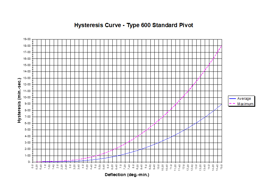
Hysteresis Curve — Type 600 Standard Pivot
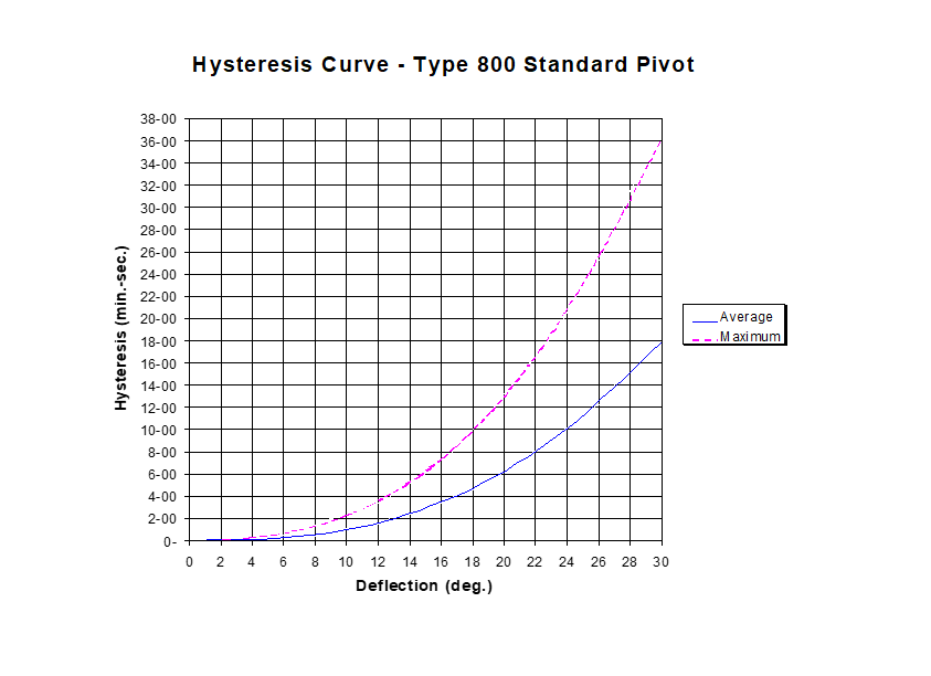
Hysteresis Curve — Type 800 Standard Pivot
Reference figures from the Riverhawk engineering data sheet.
Torsional Spring Rate
Torsional spring rate values remain constant throughout rotation.
Torsional spring rate values remain constant throughout rotation. To calculate the torsional spring rate of a pivot under load, multiply your load value by the constant found in the table of constants.
Note: In tension, the graph shows torsional spring rate values dropping below zero. In this situation, the spring would be considered unstable and would lose its ability to restore itself to the null position after being rotated.
Radial Load vs. Torsional Spring Rate
In tension, the spring rate drops below zero — the pivot becomes unstable and loses its ability to restore to null.
Pivot Stiffness Data
Radial and axial stiffness reference data for standard brazed cantilever pivots.
With reference to the flex pivot stiffness data provided in the "Dimensions and Characteristics" table, this data is for reference only and Riverhawk does not guarantee that the product will meet these values. The data was developed by empirical results (testing) obtained via an assortment of pivot types and sizes over time and represents the average values for the specific pivot groups tested.
Testing was performed on the cantilever type pivot (5000 series) loaded at the midpoint of the unsupported half. If cantilever pivots are used as a pair on a common axis and are interconnected with a very stiff piece of hardware, the radial stiffness value for each pivot can be assumed to be 1.25 times the value indicated in Table 1 — a result of the moment (cantilever) bending being restrained, putting the pivot essentially in pure shear.
A double-ended (6000 series) pivot evenly loaded in the center of its length is approximately 2.5 times the radial stiffness of an unsupported cantilever pivot, and the values in Table 1 can be increased by a factor of 2.5.
Load Vector Designations
The columns in Table 1 represent a specific load vector related to the angular orientation of the load with respect to the pivot flexures (see Figure 1 and Figure 2). The subletter "c" means compression, "t" means tension, and "a" means axial. "Compression" and "tension" refer to compression or tension stresses in the pivot flexures resulting from the applied load.
- • P load — load applied in line with the plane of a flexure.
- • V load — load vector 45° from the band between the flexures at the center of one of the arc-shaped halves.
- • Pa load — axial load applied at the pivot centerline.
The data applies only to standard brazed construction pivots.
| Catalog Number | Radial Rate | Axial Rate | |||
|---|---|---|---|---|---|
| Vc Load | Vt Load | Pc Load | Pt Load | Pa Load | |
| lb/in | lb/in | lb/in | lb/in | lb/in | |
| 5004-400 | 6,000 | 4,000 | 4,000 | 3,000 | 4,000 |
| 5004-600 | 4,000 | 2,000 | 3,000 | 2,000 | 3,000 |
| 5004-800 | 2,000 | 1,000 | 1,000 | 1,000 | 2,000 |
| 5005-400 | 8,000 | 6,000 | 7,000 | 5,500 | 8,000 |
| 5005-600 | 6,000 | 4,000 | 4,000 | 3,000 | 5,000 |
| 5005-800 | 3,000 | 2,000 | 2,000 | 2,000 | 3,000 |
| 5006-400 | 11,000 | 9,000 | 9,000 | 7,500 | 12,000 |
| 5006-600 | 7,000 | 6,000 | 6,000 | 4,000 | 8,000 |
| 5006-800 | 4,000 | 3,000 | 3,000 | 2,500 | 4,000 |
| 5008-400 | 16,000 | 13,000 | 14,000 | 11,000 | 20,000 |
| 5008-600 | 10,000 | 9,000 | 9,000 | 6,000 | 12,000 |
| 5008-800 | 5,000 | 4,500 | 4,000 | 4,000 | 7,000 |
| 5010-400 | 22,000 | 18,000 | 18,000 | 15,000 | 26,000 |
| 5010-600 | 13,000 | 12,000 | 12,000 | 9,000 | 18,000 |
| 5010-800 | 7,000 | 7,000 | 6,000 | 5,000 | 10,000 |
| 5012-400 | 27,000 | 22,000 | 23,000 | 19,000 | 34,000 |
| 5012-600 | 16,000 | 14,000 | 14,000 | 11,000 | 22,000 |
| 5012-800 | 9,500 | 8,000 | 7,000 | 6,000 | 12,000 |
| 5016-400 | 38,000 | 32,000 | 32,000 | 26,000 | 50,000 |
| 5016-600 | 22,000 | 20,000 | 21,000 | 16,000 | 32,000 |
| 5016-800 | 12,000 | 10,000 | 10,000 | 9,000 | 16,000 |
| 5020-400 | 50,000 | 40,000 | 41,000 | 35,000 | 64,000 |
| 5020-600 | 29,000 | 27,000 | 26,000 | 20,000 | 42,000 |
| 5020-800 | 16,000 | 13,000 | 12,000 | 11,000 | 22,000 |
| 5024-400 | 61,000 | 50,000 | 51,000 | 42,000 | 79,000 |
| 5024-600 | 36,000 | 33,000 | 33,000 | 25,000 | 52,000 |
| 5024-800 | 20,000 | 16,000 | 15,000 | 14,000 | 26,000 |
| 5032-400 | 83,000 | 68,000 | 70,000 | 53,000 | 110,000 |
| 5032-600 | 49,000 | 45,000 | 45,000 | 34,000 | 71,000 |
| 5032-800 | 27,000 | 22,000 | 21,000 | 19,000 | 37,000 |
Radial & axial stiffness data for standard brazed cantilever pivots · Values in lb/in · Source: Riverhawk Engineering Data
Table 1 — Radial and Axial Stiffness Data (Brazed Cantilever Pivots)
- Applies only to cantilevered (5000 series) brazed pivots loaded at the mid-point of the unsupported half at 0° deflection.
- For double-ended pivots (6000 series), multiply the Radial Stiffness values by 2.5 for the same diameter and flexure class. There is no change in axial stiffness.
- For a system of tandem-mounted cantilevered pivots (5000 series) connected very stiffly, multiply the radial stiffness values by 1.25 for each pivot in the system.
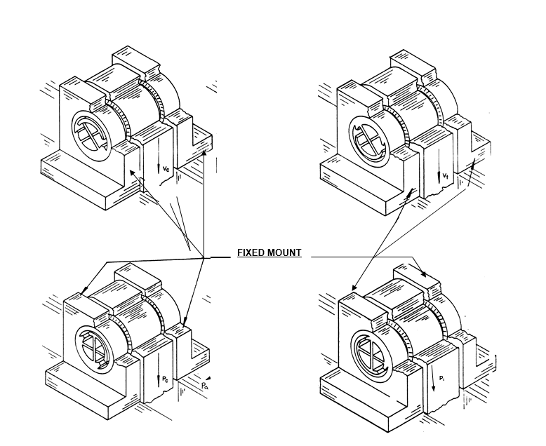
Figure 1 — Double-End Supported Pivots
Where a Pt or Vt condition exists, a Pc or Vc condition may be obtained by rotating the pivot 180° — or conversely, a Pt or Vt may be obtained from a Pc or Vc loading by rotating the pivot 180° within the fixed mount.
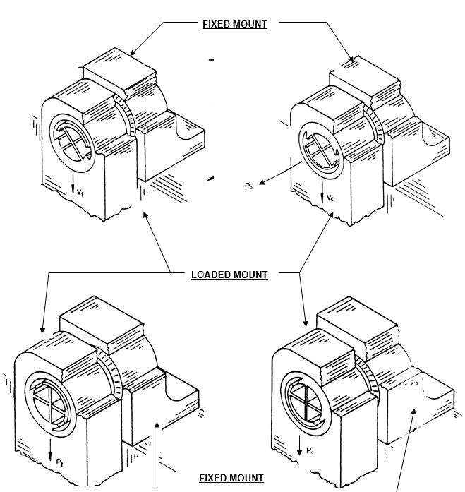
Figure 2 — Cantilever Pivots
Load orientation reference for cantilevered (single-ended) configurations, showing the relationship between the load vector and the flexure orientation.
Glossary of Flexural Pivot Terms
Standard terminology used throughout Riverhawk engineering documentation.
Axial Load
Also called 'Thrust Load'. Acts in the direction of the longitudinal axis of the pivot.
Axial Rate
Pounds of axial (thrust) load necessary to create a unit of relative motion between the flexure-connected portions in the longitudinal direction (lb/in). Example: 50 lb creates 0.001 in motion → 50,000 lb/in.
Center Shift
The difference between the diameter centers of the moved portion of the pivot and the fixed portion(s). Basic center shift is a kinematic characteristic occurring as a function of angle deflected. An auxiliary center shift is mechanical, caused by radial load.
Cycle
Angular motion from null to a particular angle, return to null, motion to the same angle in the opposite direction, and return to null.
H Load
A radial load that bisects the crossed flexures and is parallel to the travel slots.
Horizontal Load
A radial load perpendicular to 'V load'; see 'H Load' and 'V Load'.
Hysteresis
The total variation from null position when a torque is applied to produce a complete cycle. Expressed in minutes or seconds.
K
A designation for 'Torsional Rate' used in the torsional rate equation.
Linearity
The degree to which a plot of torque (about the longitudinal axis) vs. deflection is a straight line.
Moment
A torque applied in a given plane through a pivot other than around the longitudinal axis. Riverhawk Engineering usually considers it as a torque in addition to that caused by an offset V, H or T load.
Moment (Total)
The total torque applied in a given plane through a pivot other than around the longitudinal axis — the algebraic sum of moments caused by radial and thrust loads and any additional from other sources.
Moment-Turning
The torque necessary to rotate the pivot a specific angle. Related to, but not identical to, 'Torsional Rate'.
Non-Linearity
The degree to which a plot of torque (about the longitudinal axis) vs. deflection varies from a straight line; the opposite of linearity.
Null Position
The position of zero angular travel when the pivot is under no load, with no applied torque about any axis, at a specific temperature.
Null Shift
The change in null position due to effects other than applied loads and/or torques. Not to be confused with hysteresis.
Pt Load
A radial load directed directly through either the outer or inner spring which results in a tension load.
Pc Load
A radial load directed directly through either the outer or inner spring which results in a compression load.
P Load
A radial load directed exactly in line with a pivot flexure.
Radial Load
A load directed to the pivot center from any angle around the pivot circumference.
Radial Rate
Pounds of radial load necessary to deflect the pivot structure (measured at the OD) a unit of measure (lb/in). Example: 10 lb deflects 0.0001 in → 100,000 lb/in.
Radian
There are 2π radians in every 360° (circle); one radian is 57.2956+ degrees. In general, 57.3° is used.
Rate-Axial
See 'Axial Rate'.
Rate-Radial
See 'Radial Rate'.
Rate-Torsional
See 'Torsional Rate'.
Spring Rate
Riverhawk applies this term exclusively to express 'Torsional Rate'. Technically other rates are also through the springs, but they are not called spring rate.
Thrust Load
See 'Axial Load'.
Torsional Rate
The torque necessary to rotate the pivot per unit of rotating motion. Generally lb·in per radian; lb·in per degree also common. Designation 'K'.
Vc Load
A load directed to the pivot such that the highest flexure stress is compression.
Vt Load
A load directed to the pivot such that the highest flexure stress is tension.
V Load
A radial load that bisects the crossed flexures and is perpendicular to the travel slots.
Download the full Engineering Data PDF
Includes hysteresis curves, full centershift factor tables, and reference figures.