Free-Flex® Pivot Bearings
Precision flexural bearings available in cantilevered (Series 5000), double-ended (Series 6000), and custom configurations.
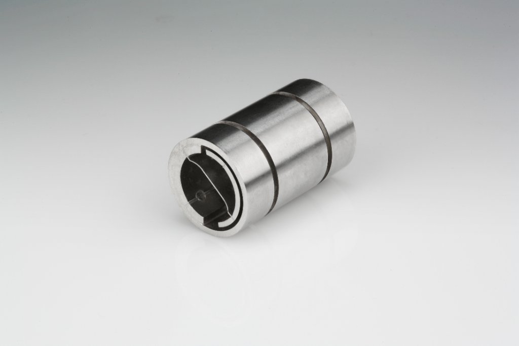
Double-Ended
Double-ended pivots bridge-support a central load from both ends. They offer higher load capacities and increased radial stiffness compared to cantilevered designs.
Key Features
Specifications
The -400, -600, -800 Designation
Each Free-Flex® pivot diameter is available in three spring thickness series, offering different balances of load capacity, spring rate, and rotational range.
Heavy Spring
Thickest spring. Highest load rating and torsional stiffness, but lowest angular range. For high-load, limited-rotation applications.
Medium Spring
Balanced spring thickness. Middle ground between load capacity, spring rate, and angular range. Most versatile option.
Light Spring
Thinnest spring. Lowest loads and spring rate, but highest angular capability. For low-load, high-rotation applications.
Interactive Size Guide
Filter by diameter, spring rate, and pivot type to find the right part number and verify dimensional and load data.
| OD (in) | Series | Part Number | Part Length L (in) | Section B (in) | Section C (in) | Vc (lb) | Vt (lb) | Max Axial Load (lb) | Spring Rate (in·lb/deg) |
|---|---|---|---|---|---|---|---|---|---|
| 0.125" | -400 | 6004-400 | 0.2" | 0.045" | 0.085" | 28 | 28 | 24 | 0.014 |
| 0.125" | -600 | 6004-600 | 0.2" | 0.045" | 0.085" | 17.7 | 25 | 12 | 0.0017 |
| 0.125" | -800 | 6004-800 | 0.2" | 0.045" | 0.085" | 2.2 | 4.7 | 5.8 | 0.0002 |
| 0.1562" | -400 | 6005-400 | 0.25" | 0.057" | 0.11" | 44 | 44 | 38 | 0.0279 |
| 0.1562" | -600 | 6005-600 | 0.25" | 0.057" | 0.11" | 27.6 | 39 | 19 | 0.0035 |
| 0.1562" | -800 | 6005-800 | 0.25" | 0.057" | 0.11" | 3.5 | 7.4 | 9.6 | 0.0004 |
| 0.1875" | -400 | 6006-400 | 0.3" | 0.067" | 0.13" | 63 | 63 | 56 | 0.0473 |
| 0.1875" | -600 | 6006-600 | 0.3" | 0.067" | 0.13" | 39.6 | 56 | 27 | 0.0057 |
| 0.1875" | -800 | 6006-800 | 0.3" | 0.067" | 0.13" | 4.9 | 9 | 14 | 0.0007 |
| 0.25" | -400 | 6008-400 | 0.4" | 0.09" | 0.175" | 113 | 113 | 98 | 0.1141 |
| 0.25" | -600 | 6008-600 | 0.4" | 0.09" | 0.175" | 70.7 | 100 | 49 | 0.0143 |
| 0.25" | -800 | 6008-800 | 0.4" | 0.09" | 0.175" | 8.5 | 19 | 25 | 0.0018 |
| 0.3125" | -400 | 6010-400 | 0.5" | 0.112" | 0.22" | 176 | 176 | 152 | 0.2234 |
| 0.3125" | -600 | 6010-600 | 0.5" | 0.112" | 0.22" | 110 | 156 | 76 | 0.0286 |
| 0.3125" | -800 | 6010-800 | 0.5" | 0.112" | 0.22" | 14 | 29 | 38 | 0.0036 |
| 0.375" | -400 | 6012-400 | 0.6" | 0.135" | 0.265" | 253 | 253 | 222 | 0.384 |
| 0.375" | -600 | 6012-600 | 0.6" | 0.135" | 0.265" | 159 | 225 | 111 | 0.048 |
| 0.375" | -800 | 6012-800 | 0.6" | 0.135" | 0.265" | 19.8 | 42 | 55 | 0.0058 |
| 0.5" | -400 | 6016-400 | 0.8" | 0.18" | 0.355" | 450 | 450 | 392 | 0.908 |
| 0.5" | -600 | 6016-600 | 0.8" | 0.18" | 0.355" | 283 | 400 | 196 | 0.1134 |
| 0.5" | -800 | 6016-800 | 0.8" | 0.18" | 0.355" | 35.4 | 75 | 98 | 0.0142 |
| 0.625" | -400 | 6020-400 | 1" | 0.225" | 0.445" | 703 | 703 | 612 | 1.85 |
| 0.625" | -600 | 6020-600 | 1" | 0.225" | 0.445" | 442 | 625 | 306 | 0.2321 |
| 0.625" | -800 | 6020-800 | 1" | 0.225" | 0.445" | 55 | 117 | 154 | 0.0295 |
| 0.75" | -400 | 6024-400 | 1.2" | 0.27" | 0.535" | 1013 | 1013 | 884 | 3.18 |
| 0.75" | -600 | 6024-600 | 1.2" | 0.27" | 0.535" | 636 | 900 | 442 | 0.398 |
| 0.75" | -800 | 6024-800 | 1.2" | 0.27" | 0.535" | 78 | 169 | 221 | 0.05 |
| 1" | -400 | 6032-400 | 1.6" | 0.37" | 0.735" | 1800 | 1800 | 1570 | 7.52 |
| 1" | -600 | 6032-600 | 1.6" | 0.37" | 0.735" | 1131 | 1600 | 785 | 0.939 |
| 1" | -800 | 6032-800 | 1.6" | 0.37" | 0.735" | 141 | 300 | 392 | 0.1175 |
30 configurations shown · L ±0.003", A/B ±0.005" · Spring rate ±10% tolerance
Life Cycle Curves
Load capacity as a percentage of rated Vc load vs. angular rotation. Use these curves with the size guide to verify your application's life requirement.
Life Cycle Curves
% of rated Vc load vs. angular rotation — from Riverhawk engineering data
- -400 (Thick)
- -600 (Medium)
- -800 (Thin)
High-cycle dynamic
Extended service
Below fatigue limit
Vc Compression load, cantilever (5000 series) · Log-scale Y axis · Source: Goodrich / Riverhawk catalog cyclic life charts
Pivot Selection Guide
Follow this process to select the right Free-Flex® pivot for your application.
Determine Mounting
Choose single-ended (cantilevered overhung load) or double-ended (bridged central load) based on your mechanical configuration.
Identify Loads
Determine the radial loads (Vc, Vt) your pivot must support. Vc = compression on flexures; Vt = tension on flexures.
Define Rotation
Establish the required angular rotation range. Select the spring series (-400, -600, -800) that accommodates your angle while meeting load requirements.
Verify Life
Use the cycle life curves to confirm infinite life at your operating angle and load. Contact engineering for application-specific verification.
Need help selecting the right pivot for your application?
Engineering Consultation