Cantilevered (Single-Ended) Flexures
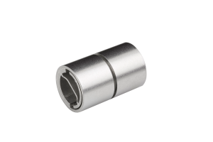
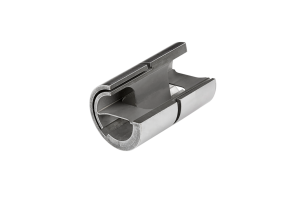
Cantilevered Free-Flex® Pivots are the most common type of flexure. Our single-ended flexures are attached or supported on one end which allows the other end to rotate. General applications include gimbal rings, mirror mounts, linkage systems and vibration isolation systems.
Features
Standard Material
Standard pivots are brazed construction and consist of an AISI 410 corrosion-resistant steel body with AISI 420 flexures.
Torsional Spring Rate
The spring rates are usually within ±10% or less of the tabulated values above. However, the tolerances can be much larger for spring rate values below .0018 in-lb/deg. Contact our engineering staff if closer tolerances or actual values are required.
Welded Construction
Electron beam welded pivots are available for applications with high applied loads and low rotational angles. Please contact Riverhawk engineering for assistance or further information.
Tighter Diameter Tolerance
For applications where a tighter diameter tolerance is required, +0.0000/-0.0002 inches, specify “T2” after the catalog number. If other tolerance variations are desired please contact our engineering staff for assistance.
CHARACTERISTICS CHART
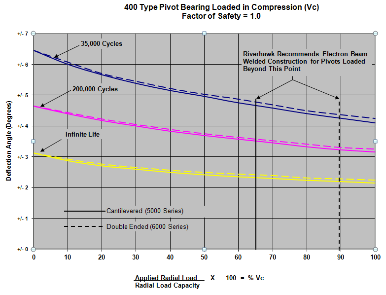
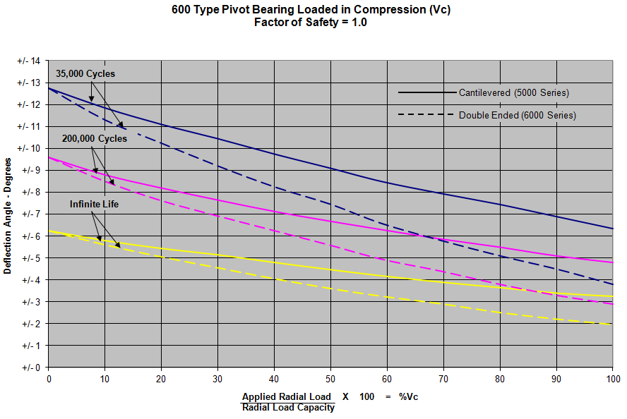
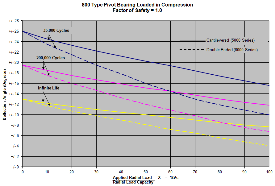
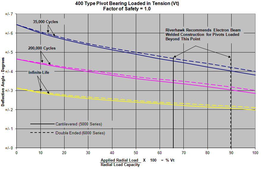
Radial load capacities noted below correspond to vertical radial loads resulting in compression (Vc) or tension (Vt) of the flexures, as depicted below.
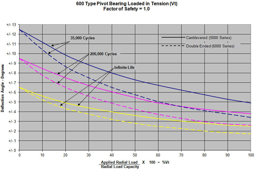
Use the Pivot Characteristics Chart PDF in combination with our life cycle curves to determine the proper pivot for your application:
| Nominal Outside Diameter (Inch) D +0.0000 -0.0005 | Catalog Number | Load Capacity – (Pounds) Load At Center of “A” | 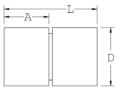 | Torsional Spring Rate See Note (2) in – lb Degree | Maximum Axial Load (lbs.) | ||
| See Note (1) | |||||||
| Series 5000 Cantilevered (size-type) | Vc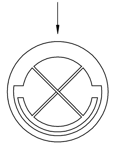 | Vt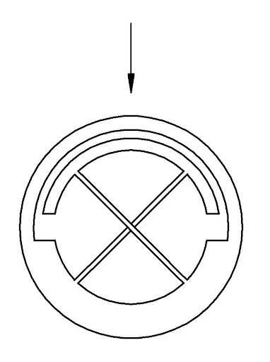 | L ±0.003 | A ±0.005 | |||
| 0.1250 | 5004-400 | 25.5 | 25.5 | 0.200 | 0.095 | 0.0140 | 24 |
| 5004-600 | 8.9 | 13.0 | 0.0017 | 12 | |||
| 5004-800 | 1.0 | 3.7 | 0.0002 | 5.8 | |||
| 0.1562 | 5005-400 | 39.5 | 39.5 | 0.250 | 0.120 | 0.0279 | 38 |
| 5005-600 | 13.8 | 20.0 | 0.0035 | 19 | |||
| 5005-800 | 1.5 | 6.0 | 0.0004 | 9.6 | |||
| 0.1875 | 5006-400 | 56.0 | 56.0 | 0.300 | 0.142 | 0.0473 | 56 |
| 5006-600 | 19.8 | 28.0 | 0.0057 | 27 | |||
| 5006-660 | 12.2 | 20.2 | 0.0037 | 27 | |||
| 5006-800 | 2.1 | 8.0 | 0.0007 | 14 | |||
| 0.2500 | 5008-400 | 101.0 | 101.0 | 0.400 | 0.190 | 0.1141 | 98 |
| 5008-600 | 35.5 | 51.0 | 0.0143 | 49 | |||
| 5008-800 | 3.7 | 14.5 | 0.0018 | 25 | |||
| 0.3125 | 5010-400 | 158.0 | 158.0 | 0.500 | 0.238 | 0.2234 | 152 |
| 5010-600 | 55.0 | 79.0 | 0.0286 | 76 | |||
| 5010-800 | 5.8 | 23.0 | 0.0036 | 38 | |||
| 0.3750 | 5012-400 | 228.0 | 228.0 | 0.600 | 0.285 | 0.3840 | 222 |
| 5012-600 | 80.0 | 114.0 | 0.0480 | 111 | |||
| 5012-800 | 8.4 | 32.8 | 0.0058 | 55 | |||
| 0.5000 | 5016-400 | 403.0 | 403.0 | 0.800 | 0.380 | 0.9080 | 392 |
| 5016-600 | 141.0 | 202.0 | 0.1134 | 196 | |||
| 5016-800 | 14.6 | 58.0 | 0.0142 | 98 | |||
| 0.6250 | 5020-400 | 634.0 | 634.0 | 1.000 | 0.475 | 1.8500 | 612 |
| 5020-600 | 222.0 | 317.0 | 0.2321 | 306 | |||
| 5020-800 | 23.0 | 93.0 | 0.0295 | 154 | |||
| 0.7500 | 5024-400 | 910.0 | 910.0 | 1.200 | 0.570 | 3.1800 | 884 |
| 5024-600 | 318.0 | 455.0 | 0.3980 | 442 | |||
| 5024-800 | 33.0 | 130.0 | 0.0500 | 221 | |||
| 1.0000 | 5032-400 | 1620.0 | 1620.0 | 1.600 | 0.770 | 7.5200 | 1570 |
| 5032-600 | 567.0 | 815.0 | 0.9390 | 785 | |||
| 5032-800 | 60.0 | 236.0 | 0.1175 | 392 | |||
| Nominal Outside Diameter (mm) D +0.0000 -0.0127 | Catalog Number | Load Capacity – N (1) Load At Center of “C” |  | Torsional Spring Rate See Note (2) N – mm Degree | Maximum Axial Load | ||
| See Note (1) | |||||||
| Series 5000 Cantilevered (size-type) | Vc | Vt | L ±0.0762 | A ±0.127 | |||
| 3.175 | 5004-400 | 113.4 | 113.4 | 5.08 | 2.413 | 1.58 | 106.8 |
| 5004-600 | 39.6 | 57.8 | 0.19 | 53.4 | |||
| 5004-800 | 4.3 | 16.5 | 0.02 | 25.8 | |||
| 3.96748 | 5005-400 | 175.7 | 175.7 | 6.35 | 3.048 | 3.15 | 169 |
| 5005-600 | 61.4 | 89.0 | 0.40 | 84.5 | |||
| 5005-800 | 6.7 | 26.7 | 0.05 | 42.7 | |||
| 4.7625 | 5006-400 | 249.1 | 249.1 | 7.62 | 3.6068 | 5.34 | 249.1 |
| 5006-600 | 88.1 | 124.6 | 0.64 | 120.1 | |||
| 5006-660 | 54.3 | 89.9 | 0.42 | 120.1 | |||
| 5006-800 | 9.3 | 35.6 | 0.08 | 62.3 | |||
| 6.35 | 5008-400 | 449.3 | 449.3 | 10.16 | 4.826 | 12.89 | 435.9 |
| 5008-600 | 157.9 | 226.9 | 1.62 | 218 | |||
| 5008-800 | 16.5 | 64.5 | 0.20 | 111.2 | |||
| 7.9375 | 5010-400 | 702.8 | 702.8 | 12.7 | 6.0452 | 25.24 | 676.1 |
| 5010-600 | 244.7 | 351.4 | 3.23 | 338.1 | |||
| 5010-800 | 25.8 | 102.3 | 0.41 | 169 | |||
| 9.525 | 5012-400 | 1014.2 | 1014.2 | 15.24 | 7.239 | 43.39 | 987.5 |
| 5012-600 | 355.9 | 507.1 | 5.42 | 493.8 | |||
| 5012-800 | 37.4 | 145.9 | 0.66 | 244.7 | |||
| 12.7 | 5016-400 | 1792.6 | 1792.6 | 20.32 | 9.652 | 102.59 | 1743.7 |
| 5016-600 | 627.2 | 898.5 | 12.81 | 871.9 | |||
| 5016-800 | 64.9 | 258.0 | 1.60 | 435.9 | |||
| 15.875 | 5020-400 | 2820.2 | 2820.2 | 25.4 | 12.065 | 209.02 | 2722.3 |
| 5020-600 | 987.5 | 1410.1 | 26.22 | 1361.2 | |||
| 5020-800 | 102.3 | 413.7 | 3.33 | 685 | |||
| 19.05 | 5024-400 | 4047.9 | 4047.9 | 30.48 | 14.478 | 359.29 | 3932.2 |
| 5024-600 | 1414.5 | 2023.9 | 44.97 | 1966.1 | |||
| 5024-800 | 146.8 | 578.3 | 5.65 | 983.1 | |||
| 25.4 | 5032-400 | 7206.1 | 7206.1 | 40.64 | 19.558 | 849.64 | 6983.7 |
| 5032-600 | 2522.1 | 3625.3 | 106.09 | 3491.9 | |||
| 5032-800 | 266.9 | 1049.8 | 13.28 | 1743.7 | |||
- Pounds at zero deflection based on pure radial load. When the load is applied directly through a single spring, multiply capacity by 0.707. Pivot orientated such that a radial load puts flexures in Compression (Vc) or Tension (Vt).
- At zero load.
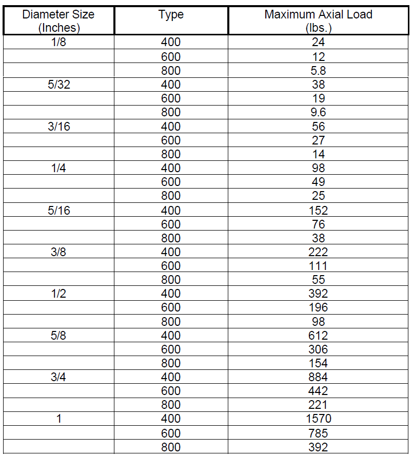
Axial Load Capability for Free-Flex Pivots
Note: The maximum axial loads listed below are for pivots loaded in a purely axial direction.
For combined radial and axial loading contact TRW Utica Engineering.
To learn more about Riverhawk’s Cantilevered (Single-Ended) Pivot Bearing, please contact a member of our team. We are happy to assist you with your project needs.

